|
| OO Scale | N Scale | G Scale | Z Scale | HO Scale | Slot Cars & R⁄C |
| |||||||
|
|||||||
| Home Page | |||||||
| BUY GIFT VOUCHERS | |||||||
| Products | |||||||
| Latest News | |||||||
| RIGHT LINES | |||||||
| Bargains | |||||||
| Downloads | |||||||
| Events | |||||||
| Careers & Jobs | |||||||
| Carriage Services | |||||||
| About Us | |||||||
| Contact Us | |||||||
| Pay Us A Visit | |||||||
| Meet The Staff | |||||||
| Links | |||||||

| SHOPPING BASKET |
Your shopping basket is empty. To add an item, click the "Buy" button
| YOUR ACCOUNT | ||
|
||||
 |
||||
| Prodigy Advance Digital System |
||||
| Cased Controllers |
||||
| Panel Mount Controllers |
||||
| Walkabout Controllers |
||||
| Modules & Transformers |
||||
| Scenics & Accessories |
||||
| Wiring & Electrical Components |
||||
| Tiny Signs | ||||
| Tools | ||||
 |
||||
| RECENTLY VIEWED |
| PR79145 - Passengers in front of Timetable Figure Set | ||
| PR79055 - Hay Harvesters (6) Figure Set | ||
| ODNQ1007 - Q1 BUT Trolleybus Cardiff (Streamline) | ||
| PK62228 - Red River Station Kit | ||
| PK62814 - North Pole Icicles Set | ||
| More ›› |
| O Scale | Wargaming | Architectural | Narrow Gauge | Tools+ | ||
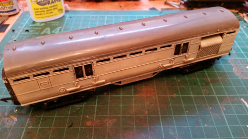
Converting a Triang Royal Mail Van Part 3

WARREN KERFOOT converts a third Triang Royal Mail Van to run on modern track.
Here's a third coach created on the back of an article regarding Royal Mail coaches being modified by using the early Triang TPO units which appeared some time back in a magazine.
The first and second were a sorting van and a 60' LMS diagram stowage van, whereas this one is the much shorter 42ft LMS diagram stowage or tender vehicle. The information I worked to said there was only one of these made and it didn't run on routes in my layout's area... but I'm not one to get bogged down in the detail! It's more about having a good few evenings of fettling something useless into something interesting and attractive.
This particular one means the destruction of technically four Triang R23 units, but you could by this stage have a build up of cut parts as I did from the previous jobs. As before, hopefully the result is a model that's a lot more pleasing to the eye, more like a prototype, more interesting, and actually runs on modern track. You may have seen my previous two articles (here and here) on these conversions, so please excuse the repetition for those who are just picking up my ramblings!
All that's needed in terms of tools is the GM679 Gaugemaster Universal Razor Saw as it has a deeper cut, GM676 Aluminium Mitre Box, GM608 Bent Nose Pliers, a square and some files, plus of course a cutting mat. Not for the obvious reason of it just being a cutting mat, but the usefulness of the printed lines to keep the model square as it is constructed bit by bit.
Again, remove the bogies first. These are fixed originally by a soft brass fixing, so just nip the rolled over edge in a few places on the bogie underside and collapse the walls inwards using the bent nose pliers. All a bit brutal but effective as these parts are scrap. Then remove the underframe. There are two generations of these it seems, one is retained by the roof fixing screw and the other is clipped in place, though I did come across one that had been bonded. Which ever you encounter it needs to be removed and you may want to re-use it, so gently does it.
The roof is a straightforward removal, and then the inner workings are exposed. The mailing unit is simply held in place by four lugs along the top of the vehicle sides. Just ease the body sides apart gently and the unit releases pretty readily. There's three of these to do for this particular model though!
For this stowage vehicle there are lots of cuts requiring the saw where the door recesses are going to be made. The moulded traductors are carved off initially with the trusty GM knife and then filed smooth. Same goes for the dummy side lamps and any ribbing in the moulding.
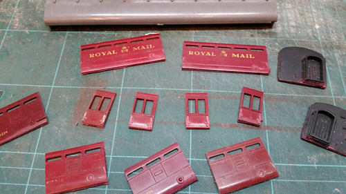
Then the cuts... You pretty much need everything off the twin door side cut neatly - with the door side facing you - run down the end of each of the doors (very tightly into the moulding as you need the moulding either side of each cut too).
Now run along the solebar to where it meets the tumblehome of the body side with the saw end only. Keep slicing in with the end of the saw until a defined cut starts. It's too long to cut without this as a guide. It isn't necessary thankfully to work all the way through, it is just going to be a fracture line, but the cut prevents any strain going into the upper body causing a crack or distortion on the bits you want.
Looking inside now, nip off all the supporting pegs and frames for the body that are right behind the side you've cut then, section by section, push each piece backwards until it obligingly snaps clean off.
For this vehicle you do have to have to contend with a window anomaly. The end panels are two window units, not three as you'll have now. The only practical solution I found for this to keep the vehicle length correct was to cut out the window dividers and then refit one in the centre. This takes a bit of careful slicing and cleaning up. It now gives you twin window ends, albeit they are larger than the glazing in the centre five panel section between the doors. Looking at the photos of the real vehicle I convinced myself that this is prototypical.
Remove the ends (mirror cut of what you did down the old twin door side), then I cut along just above the buffer holes and just below the corridor connector. The original author of the article I read which set this ball rolling, he cut the full ends off - but I wanted to make new bufferbeams and it also helps keep the body structure all at 'one level' as you make it back up.
Now it's file time. Each piece needs cleaning up to remove debris and lumps. Take your time and get each piece tidy and square as it'll make the rebuild so much easier. This model's supposed to be 42' in length, so 168mm when converted to OO Scale. It really is a crude and simple process of laying the pieces down piece on piece. Remember for the doors to get the length as good as possible. It's actually come out at 41'6 so that's good enough for me.
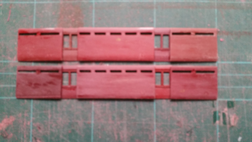
For regluing I use DLAD-70 Deluxe Materials Plastic Kit Glue for these as the type of plastic responds really well to it. When all the joints and so on are cured a whip round with Deluxe Materials Perfect Plastic Putty to fill in collateral damage and any random gaps in the final fit.
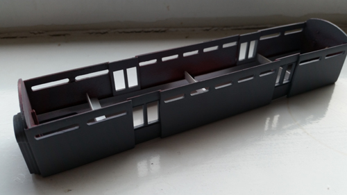
Once you have the sides and ends glued and squared up (just using the lines on the cutting mat) you have something resembling a coach but very weak, so Plastruct angle is used to brace the inside along its length and spacers carefully measured and fitted laterally. Leave that to cure overnight ideally and you end up with a decent rigid structure.
The roof is shorter in length, ventilators filed off and some proper ventilators refitted as well as rainstrips from fine Plastruct. Then quickly prepare for repainting with a fibre glass pencil. The GM633 Glass Fibre Pencil is best and gives a brilliant key for the repaint.
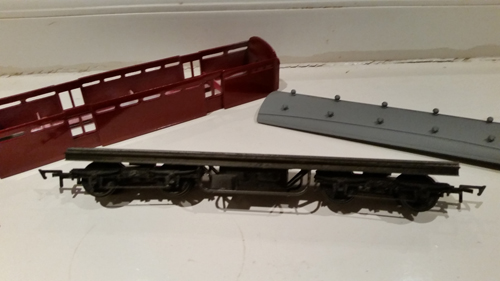
For this particular model I needed a new chassis. This is made up of 80 thou plastic card and the underframe made from various fine Plastruct pieces, and tried to capture some of the slightly different gear fitted to this particular vehicle's underside. I made up Ratio ex LNWR LMS bogies again for this one.
The model is primed and then topcoated when anything too bad is dealt with. I get a little bit 'eager' at this stage as I want to see the end result, but taking your time and allowing each coat to cure out properly is crucial
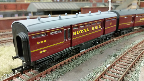
Then using HMRS LMS Coach decals for my beloved LMS, as well as the lining sheet to create a mid 1930's livery style. If you like the windows to look flush as I do run DLAD-55 Deluxe Materials Glue N Glaze in over the acetate windows you've fitted behind and the effect is tremendous. Hopefully, what was an unusable and crude vehicle at origin takes on it's new guise. Not designed to be a slavish copy of it's diagram, just to give the feel of a different unit in a Royal Mail TPO running set.
|


We are always looking to make improvements to our website to try and improve the quality of your visit. We would welcome your feedback and suggestions, so please do not hesitate to e-mail our webmaster with your comments. Alternatively call us on 01903 884488.
Home Cookies Privacy Statement Terms & Conditions Site Map Site Guide
WEEE Regulations Glossary Careers & Jobs
Tel – +44 (0) 1903 884488 Fax – +44 (0) 1903 884377 E-Mail us – click here
Gaugemaster.com is a trading name of Gaugemaster Controls Ltd.
Registered in England No. 2714470, Registered office:
Gaugemaster House, Ford Road
Arundel, West Sussex, BN18 0BN, United Kingdom
VAT Reg. No. 587 8089 71
Copyright © 2003-2014 Gaugemaster Controls Ltd. All Rights Reserved.