|
| OO Scale | N Scale | G Scale | Z Scale | HO Scale | Slot Cars & R⁄C |
| |||||||
|
|||||||
| Home Page | |||||||
| BUY GIFT VOUCHERS | |||||||
| Products | |||||||
| Latest News | |||||||
| RIGHT LINES | |||||||
| Bargains | |||||||
| Downloads | |||||||
| Events | |||||||
| Careers & Jobs | |||||||
| Carriage Services | |||||||
| About Us | |||||||
| Contact Us | |||||||
| Pay Us A Visit | |||||||
| Meet The Staff | |||||||
| Links | |||||||

| SHOPPING BASKET |
Your shopping basket is empty. To add an item, click the "Buy" button
| YOUR ACCOUNT | ||
|
||||
 |
||||
| Prodigy Advance Digital System |
||||
| Cased Controllers |
||||
| Panel Mount Controllers |
||||
| Walkabout Controllers |
||||
| Modules & Transformers |
||||
| Scenics & Accessories |
||||
| Wiring & Electrical Components |
||||
| Tiny Signs | ||||
| Tools | ||||
 |
||||
| RECENTLY VIEWED |
| FM6526 - Spare Coupling with Rivet and Slot Fitting | ||
| FA180914 - Blue Dumpsters (2) Kit | ||
| OD76SHL06WF - Stobart Lorry Tony McCoy | ||
| PR45212 - Hand Cart/Barrow/Tools Kit | ||
| PR28136 - Couple Standing Figure | ||
| More ›› |
| O Scale | Wargaming | Architectural | Narrow Gauge | Tools+ | ||
Point Motors - Part 1: Solenoid Basics

MATT LOVELL shows us the basics when using solenoid point motors.
Points (or turnouts) are a very important part of any railway, whether it be a rural junction or a mainline station. The controlling of these points is the responsibility of the signalman, who would pull leavers in sequence to throw the point left or right depending on the timetable.
Different Types of Point Motors
For model railway use there are lots of different ways to throw points. In the early days modellers used wire in a tube, inserting a length of piano wire through a metal or plastic tube and attaching it to a tie-bar on the point. The wire was then pulled and pushed to throw the point in the required direction.
This slightly fiddly method can be avoided by using point motors, by far the most common way of changing points today.
Solenoid point motors use two solenoids connected to a suitable power supply to pull a pin towards them. This pin is attached to the tie bar and throws it in the required direction. Solenoid motors come in all shapes and sizes and can be used both above and under the baseboard depending on the design of the railway (and the motor). Point motors mounted under the board can be easily hidden out of sight, but above mounted motors can be used over joints and hard to reach areas where an under board motor will not fit. We always recommend installing a Capacitor Discharge Unit to ensure efficient point throwing.
There are also Slow Action point motors available to enable the point to be thrown slowly, which will add a more realistic feel to the railway. We will look at these in greater detail in a future issue.
Wiring a point motor normally consists of three wires - a Common, which provides power to the motor, and two switch wires which when activated complete the circuit to either throw the point motor pin left or right.
Switches
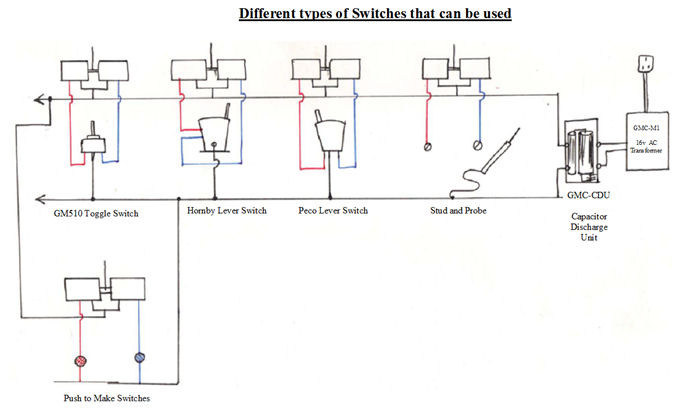
Click image to view larger version.
To throw your solenoid point motors various different methods can be used and each one has both pros and cons so it is really a personal choice as to which ones you wish to use. Below are the different types of switches that can be used.
Toggle Switch:
Also known as a Single Pole Double Throw Centre Off (SPDT) switch, these switches consist of a centre common tag which needs to be connected to a suitable power supply, and a left and right switch wire which both need to be connected to the point motor to operate.
Click Here to view available Toggle Switches.
Lever Switches:
Designed to mimic the levers in a signal box, these switches operate front to back and usually use a passing contact method to pulse the point motor left and right. These switches are similar to the toggle switches in terms of they need a common connecting to the power supply, and two switch wires which are connected to the point motor.
Click Here to view available Lever Switches.
Push Button Switches:
These switches require a bit more wiring up but are useful for control panels as they can be easily colour-coded to match the district of the layout. To wire up these switches you need to create a common wire by joining two of the tags on the switches together and running this wire back to the power supply. The remaining two tags can then be run to the point motor to operate it left and right.
Click Here to view available Push to Make Switches.
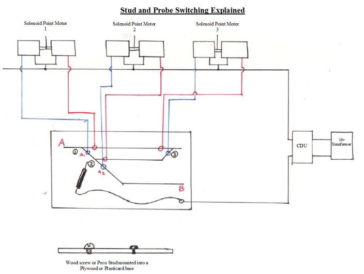
Stud and Probe:
This method is a particular favourite of mine as it is used mostly for control panels and quite an easy design to install into the railway. There are two parts to this method but as long as you are confident with a soldering iron you will be fine.
The Probe links to the power supply and acts as the common and the Studs link on to the left and right contact on the point motor. The operation is simple as all you need to do is tap the stud to throw the motor in the required direction.
Click Here to view the available parts to make a Stud and Probe system.
We can now move onto the positioning of switches on a control panel.
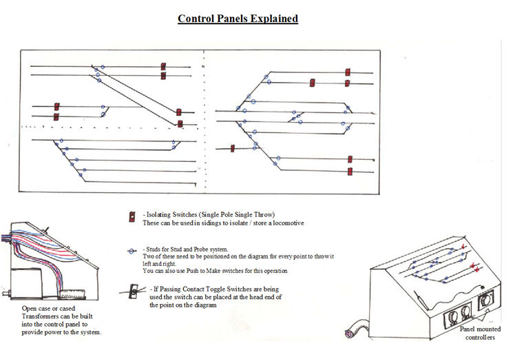
Click image to view larger version.
A control panel is a mimic diagram that modellers use to see where on the railway points are located without having to look over the railway. These are ideal for large railways or exhibition layouts which require multiple users. The panels are normally constructed with transformers installed in a box with all the electronics and power hidden away. The mimic panel can be constructed out of either plywood or plasticard, and includes a plan of your railway or sections of the whole layout.
Positioning of the switches on these panels is fairly critical as if they are not in the right place it could be confusing to other users and may cause derailments or collisions.
If you are using either the Push Button or Stud and Probe method you have some flexibility as to where to put them on the diagram, as long as they are attached to the correct line on the diagram you will know which point they activate.
Click image to view larger version.
If you are using Toggle switches you will need to position them at the mouth of the point on the diagram.
Lastly if you are using Lever Switches they can be set in a bank on the control panel with attached numbers which can be duplicated on the mimic diagram to show which point motor is activated by which switch.
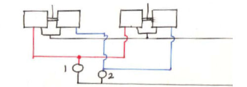
In locations that require two motors to be thrown at once like crossovers, all you need to do is work out which wire operates the correct tie-bar in the required direction and then link those wire together on the same output on the switch. This saves having to throw two different switches to get the same result.
This method can be quite useful for large stations or goods yards where two motors will need to work together to allow the locomotive to enter certain sidings or Platforms.
As you can see point motors are very useful addition to your model railway, and with the combination of the desired switching system you will find railway electronics an interesting venture.
Frequently Asked Questions
Q: Why does point motor makes a buzzing sound during operation?
A: This sound is made when the 16v supply is being pulled across the solenoid. It is perfectly normal but can be overcome by adding a CDU (Capacitor Discharge Unit) into the circuit.
Q: How many points can I run off a capacitor discharge unit?
A: You can use one CDU to wire up the whole layout, but actual operation you will be limited to up to three at a time.
Q: What switches do I need to operate my Hornby points?
A: As the Hornby motors are solenoids you can use any of the switching methods described in the article.
Q: Can I operate more than one point motor with one switch to create a crossover from track 1 to track 2?
A: Yes, all you would need to do is locate the wires that throw the point motors in the direction you want and wire them into one half of the switch (Left Switch wire) and attach the others to the other side (Right Switch wire)
Q: What power supply do I need to power my point motors?
A: Solenoid motors can take a 16v AC supply (either a M1 or WM1 transformer will be fine) but if you wire them up with a CDU in the circuit they can take up to 24v AC (a M3 transformer will be fine for this). Personally I always use a 16v supply with a CDU (Capacitor Discharge Unit) connected to the transformer output to give a nice positive thump across.
|


We are always looking to make improvements to our website to try and improve the quality of your visit. We would welcome your feedback and suggestions, so please do not hesitate to e-mail our webmaster with your comments. Alternatively call us on 01903 884488.
Home Cookies Privacy Statement Terms & Conditions Site Map Site Guide
WEEE Regulations Glossary Careers & Jobs
Tel – +44 (0) 1903 884488 Fax – +44 (0) 1903 884377 E-Mail us – click here
Gaugemaster.com is a trading name of Gaugemaster Controls Ltd.
Registered in England No. 2714470, Registered office:
Gaugemaster House, Ford Road
Arundel, West Sussex, BN18 0BN, United Kingdom
VAT Reg. No. 587 8089 71
Copyright © 2003-2014 Gaugemaster Controls Ltd. All Rights Reserved.