|
| OO Scale | N Scale | G Scale | Z Scale | HO Scale | Slot Cars & R⁄C |
| |||||||
|
|||||||
| Home Page | |||||||
| BUY GIFT VOUCHERS | |||||||
| Products | |||||||
| Latest News | |||||||
| RIGHT LINES | |||||||
| Bargains | |||||||
| Downloads | |||||||
| Events | |||||||
| Careers & Jobs | |||||||
| Carriage Services | |||||||
| About Us | |||||||
| Contact Us | |||||||
| Pay Us A Visit | |||||||
| Meet The Staff | |||||||
| Links | |||||||

| SHOPPING BASKET |
Your shopping basket is empty. To add an item, click the "Buy" button
| YOUR ACCOUNT | ||
|
||||
 |
||||
| Prodigy Advance Digital System |
||||
| Cased Controllers |
||||
| Panel Mount Controllers |
||||
| Walkabout Controllers |
||||
| Modules & Transformers |
||||
| Scenics & Accessories |
||||
| Wiring & Electrical Components |
||||
| Tiny Signs | ||||
| Tools | ||||
 |
||||
| RECENTLY VIEWED |
| FA180914 - Blue Dumpsters (2) Kit | ||
| ODNFT034 - Ford Transit MkV Van Parcelforce | ||
| B36-082 - Pigs (10) Figure Set | ||
| GF42-146 - Scenecraft Highley Station Yard Crane (Pre-Built) | ||
| N00260 - Spring Meadow Mid Green Grass Mat 120x60cm | ||
| More ›› |
| O Scale | Wargaming | Architectural | Narrow Gauge | Tools+ | ||
Wiring a Common Section Layout

JAMES HICKMAN responds to a customer who needed help wiring a common section on a layout, and we thought the response might help other modellers with a similar conundrum.
We received the following email from a customer:
"Here's a problem I'm facing at the moment. I have two loops, one outside and one inner - so my layout looks bit like normal oval apart from bottom straight where two tracks join. outer train travels left to right, inner right to left.
The two loops needs to share a single track (in my case single track suspension bridge), I need for one train to see that the track is clear can carry on over bridge - meanwhile if the second train (inner) arrives near bridge and the bridge is in use, it slows to stop waits till track is clear then slowly starts up and carries on in opposite direction over bridge. I want all of this to be done automatically by electronics/relays etc.
From reading through the questions and comments in the email I have come up with a workable solution. The only sacrifice that you would have to make would be having the locomotive slowing down before stopping to allow the other train to pass. In this instance you would find that the locomotives will enter the dead sections and stop to a halt. A possible solution to allow the locomotive to slow to a stop would be to install a capacitor into the circuit, but as this is not something we have ever tested, it is not something I could advise on. Moving forward, I have created a circuit diagram which allows the movement of stock that you require, see below:
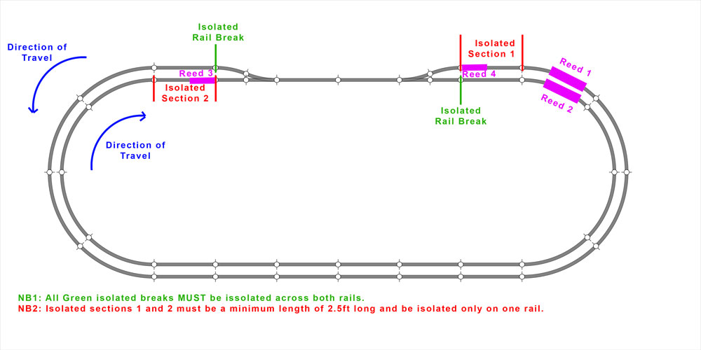
Click for larger version.
Once this is set up you will need to wire the components in as follows, using a DCC Concepts decoder, powered form a standard 16v AC supply.
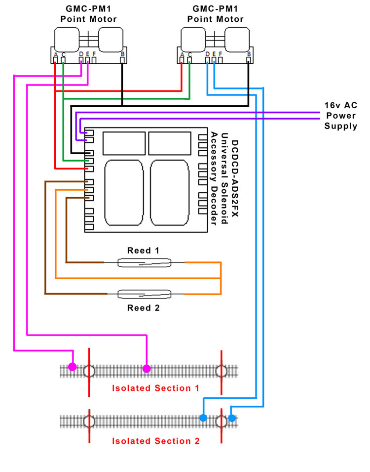
Click for larger version.
This will allow the changing of the motors automatically when the train passes over the reed switches. To activate the switches a magnet will need to be attached under the leading bogie, these are available from DCC Concepts. The only other issue is the common section of track requiring a changeover of polarity, this is sorted by following the final diagram, utilising our Gaugemaster GM500 Relay:
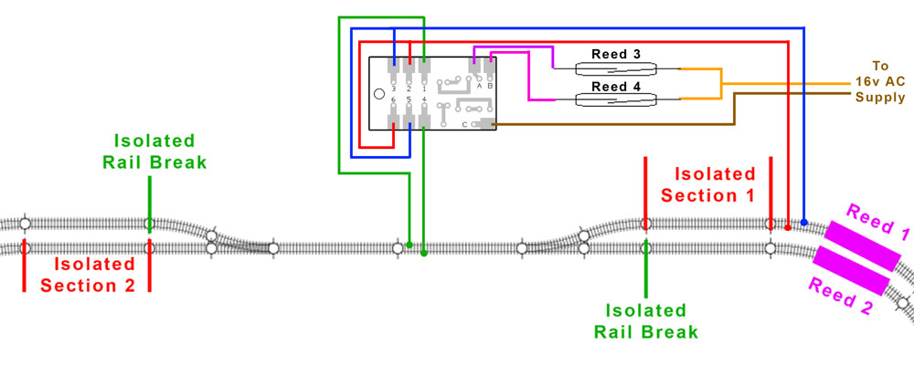
Click for larger version.
For your own layout you may need to modify the wiring, depending on the exact layout of your track. It may be a case of you needing to switch a couple of wires over on a couple of components. An example of this would be if one of your motors is throwing in the wrong direction you would need to swap wires on terminals A and B of the motor. My advice would be to wire it in as described, and if you have any other questions or problems, feel free to contact me. The list below is the additional components you would require:
GM99 Pack of Reeds and Magnets
DCDCD-ADS2FX Universal Solenoid Accessory Decoder (2 Output)
If you have any questions on this layout, you can contact him by email HERE, or pop into our shop!
|


We are always looking to make improvements to our website to try and improve the quality of your visit. We would welcome your feedback and suggestions, so please do not hesitate to e-mail our webmaster with your comments. Alternatively call us on 01903 884488.
Home Cookies Privacy Statement Terms & Conditions Site Map Site Guide
WEEE Regulations Glossary Careers & Jobs
Tel – +44 (0) 1903 884488 Fax – +44 (0) 1903 884377 E-Mail us – click here
Gaugemaster.com is a trading name of Gaugemaster Controls Ltd.
Registered in England No. 2714470, Registered office:
Gaugemaster House, Ford Road
Arundel, West Sussex, BN18 0BN, United Kingdom
VAT Reg. No. 587 8089 71
Copyright © 2003-2014 Gaugemaster Controls Ltd. All Rights Reserved.