|
| OO Scale | N Scale | G Scale | Z Scale | HO Scale | Slot Cars & R⁄C |
| |||||||
|
|||||||
| Home Page | |||||||
| BUY GIFT VOUCHERS | |||||||
| Products | |||||||
| Latest News | |||||||
| RIGHT LINES | |||||||
| Bargains | |||||||
| Downloads | |||||||
| Events | |||||||
| Careers & Jobs | |||||||
| Carriage Services | |||||||
| About Us | |||||||
| Contact Us | |||||||
| Pay Us A Visit | |||||||
| Meet The Staff | |||||||
| Links | |||||||

| SHOPPING BASKET |
Your shopping basket is empty. To add an item, click the "Buy" button
| YOUR ACCOUNT | ||
|
||||
 |
||||
| Prodigy Advance Digital System |
||||
| Cased Controllers |
||||
| Panel Mount Controllers |
||||
| Walkabout Controllers |
||||
| Modules & Transformers |
||||
| Scenics & Accessories |
||||
| Wiring & Electrical Components |
||||
| Tiny Signs | ||||
| Tools | ||||
 |
||||
| RECENTLY VIEWED |
| OD76RRS003 - Range Rover Sport SVR Firenze Red | ||
| PR14006 - Teenage Girls (6) Standard Figure Set | ||
| B36-082 - Pigs (10) Figure Set | ||
| B36-081 - Cows (7) Figure Set | ||
| B36-080 - Horses (7) Figure Set | ||
| More ›› |
| O Scale | Wargaming | Architectural | Narrow Gauge | Tools+ | ||

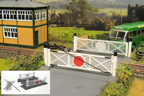
Creating an Operating Fordhampton GM404 Level Crossing

JAMES HICKMAN shows us how to modify this kit to create an operating version.
We see many layouts on the exhibition circuit these days with working barriers on their level crossings, but rarely do we see moving gates. Yes, I know we don't have the luxury of our little OO Scale crossing keeper coming to do the job for us, but it isn't that hard to do - especially with the use of servos. The first electronic servo was used in 1880 as part of Elicha Grays' Telautograph; an analogue predecessor of the fax machine (Don't worry I had to look up what a telautograph was too). Nowadays modellers in the model boat or radio controlled car fields use them regular, but it is only recently they have come to be used in actual model railways more than 'just an experiment'.
Within this article I hope to show you how servos can be used to create a working crossing gate. This said their uses don't stop there - servos can be used to move various items on your layouts, from working cranes and dumper trucks, to signals and even figures, but we'll look at those another day! With that all in mind, let's look at how easy it is.
Step 1
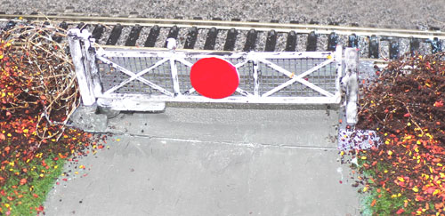
For this job I am using the Gaugemaster GM404 Fordhampton Level Crossing, but this method can be used to motorise any crossing with a gate. Hornby, Peco and Ratio all produce gated level crossings than can be motorised using this method.
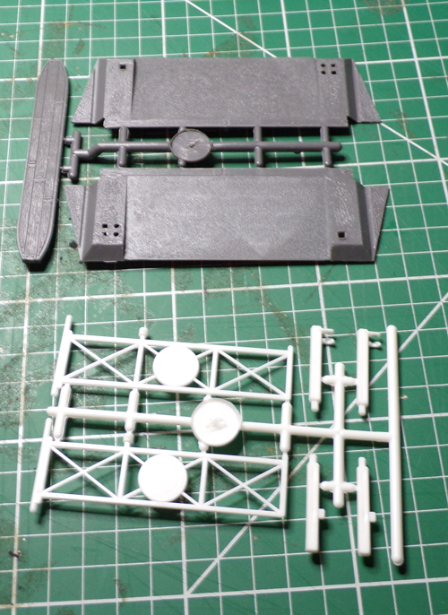
These are the components of the kit. N.B: Being as clumsy as I am, the wire mesh that is included in the kit was actually on the floor when this photo was taken, and is therefore not visible. Now simply remove these items from their sprues. For this demonstration I am only going to animate one side of the crossing as the process is identical for the second side.
Step 2
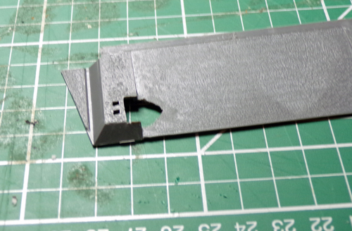
Next cut a hole in the base big enough to allow your servo gear to fit through. Remember: always cut a smaller hole than you think you will need, you can always remove a little extra plastic where as adding it back in is a difficult task.
Step 3
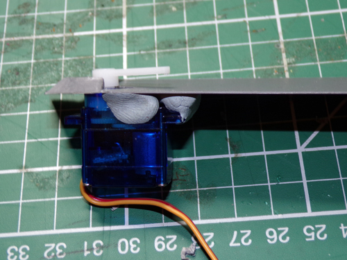
Now put the servo into place. As you can see I have only held the servo in place with blu tack at this point, this allows the servo to be tested, and see if the full throw can be achieved.
Always perform a 'dry run' to check to see if everything fits and works before committing to the glue. The image shows the servo with a servo arm attached.
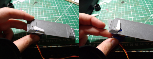
Step 4
Attach the gate. Because of the material the servo arm is made of, gluing the gate on proved to be a little tricky at first. A standard plastic glue wouldn't work so I opted for a superglue; Deluxe Materials Rocket MAX. A little trim was required for the base of the gate where it attaches to the servo arm, but this was simply done with a steady hand and a scalpel, although a file would have worked just as well. Here you can also attach the servo to the underside of the ramp, making sure not to clog up any mechanical parts with glue.
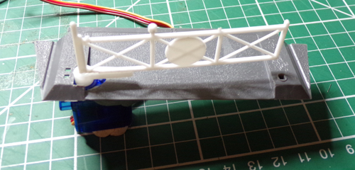
Step 5
Click to play video.
The final test of the mechanism. Note the blu tack remain in place while the glue on the other side dries.
Step 6
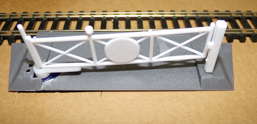
The final part of the installation is the placement of the crossing on the layout. A hole will need to be made in the baseboard to allow the motor to sit through. Once this is done reconnect the servo and give it a final test.
Step 7
That's it, now you can blend the crossing into it's new home, and if like me you can still see some of the servo after installation it's time to do some covering up.
Hopefully this has given you some inspiration to have a go at motorising some of those other items round your layouts. The only thing I haven't mentioned in this article is how the servo is powered and controlled. Unfortunately there isn't enough space to explain that in this article, but for reference it isn't difficult either. Connections from your servo (3 wires usually attached to a 3-pin plug) go to your servo control. Depending on the manufacturer the control will control one, four or multiple servos depending on it's capabilities. For those of you starting out with servos, I would recommend the Faller FA180725 Servo Control, with either two or four FA180726 Servos depending on the number of gates your crossing has.
Good luck with your own servo control projects, we would love to hear from you about any other uses you have for servos on your layouts, send to the usual address - rightlines@gaugemaster.co.uk.
|


We are always looking to make improvements to our website to try and improve the quality of your visit. We would welcome your feedback and suggestions, so please do not hesitate to e-mail our webmaster with your comments. Alternatively call us on 01903 884488.
Home Cookies Privacy Statement Terms & Conditions Site Map Site Guide
WEEE Regulations Glossary Careers & Jobs
Tel – +44 (0) 1903 884488 Fax – +44 (0) 1903 884377 E-Mail us – click here
Gaugemaster.com is a trading name of Gaugemaster Controls Ltd.
Registered in England No. 2714470, Registered office:
Gaugemaster House, Ford Road
Arundel, West Sussex, BN18 0BN, United Kingdom
VAT Reg. No. 587 8089 71
Copyright © 2003-2014 Gaugemaster Controls Ltd. All Rights Reserved.