|
| OO Scale | N Scale | G Scale | Z Scale | HO Scale | Slot Cars & R⁄C |
| |||||||
|
|||||||
| Home Page | |||||||
| BUY GIFT VOUCHERS | |||||||
| Products | |||||||
| Latest News | |||||||
| RIGHT LINES | |||||||
| Bargains | |||||||
| Downloads | |||||||
| Events | |||||||
| Careers & Jobs | |||||||
| Carriage Services | |||||||
| About Us | |||||||
| Contact Us | |||||||
| Pay Us A Visit | |||||||
| Meet The Staff | |||||||
| Links | |||||||

| SHOPPING BASKET |
Your shopping basket is empty. To add an item, click the "Buy" button
| YOUR ACCOUNT | ||
|
||||
 |
||||
| Prodigy Advance Digital System |
||||
| Cased Controllers |
||||
| Panel Mount Controllers |
||||
| Walkabout Controllers |
||||
| Modules & Transformers |
||||
| Scenics & Accessories |
||||
| Wiring & Electrical Components |
||||
| Tiny Signs | ||||
| Tools | ||||
 |
||||
| O Scale | Wargaming | Architectural | Narrow Gauge | Tools+ | ||
Points and Panels

JAMES HICKMAN explains how to create a mimic panel for point control.
Installing a point motor is easy to do on any layout. What isn't as easy is knowing which point is pointing in which direction - this is where a mimic panel comes in. It is a panel representing the track layout that uses LEDS to show which way the points are set, allowing you to see even the furthest points setting.
The panel itself can be a separate board located next to your switches or integrated with either the switches or a stud and probe method. Both these examples are included within this article.
Parts Required
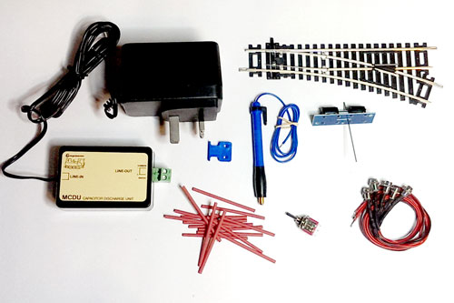
- One point motor per point being installed (GMC-PM1)
- Switch (GM510) OR two Studs (PEPL-18) and one probe (PEPL-17)
- Layout Wire
- Heat Shrink and a Lighter OR a Terminal Block (GM77)
- LEDs, either pre-wired from DCC Concepts, or from Gaugemaster which requre a resistor.
- CDU with built-in resistor (GMC-MCDU)
- Plasticard or wood to make mimic panel
- Separate 12v power supply
Tools Required
- Soldering Iron and Solder
- A Drill with 9mm and 6mm drill bits
- Screws (2 per Point Motor)
- Wire cutters / strippers
- Screwdriver
- A Lighter
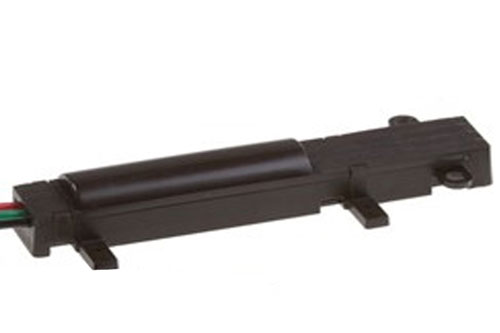
To begin to motorise your points you will need a Point motor. These are devices that fit to the point and allow the motor to throw to either side at the touch of a button or switch. There are different types of motor on the market, and each type offer something different. The three different kinds are under board motors, surface mounting motors, and slow action motors.
Under board mounting motors
These motors, as the name suggests are mounted under the board. They either clip directly to the bottom of the point, or require attaching to the board below. These motors are perfect for those situations where there is space under the board to house them, and allow the motors to be hidden away from general view. They offer the ability to be able to control frog switching, signals, and mimic diagrams.
Surface mounting motors
As you may have guessed, these motors are designed to be mounted on top of the board. They are quick and easy to install as you don't need to cut out any holes for the motor mechanism to interact with the point. Instead they sit next to the motor on the side and have a little mechanism connected to the tie bar of the point. The one down side of these motors is that they are currently unable to control anything other than the throw of the points.
Slow action motors
These motors offer a different method of point control. The aforementioned motors both give a quick throw of the point motor, which is prototypically unrealistic. Slow action motors give a much more realistic throw to the points, mimicking that of an actual point throw. Although they may be more expensive than the other types of motor they do allow control of more than one other function, for example frog switching and mimic panel LEDs.
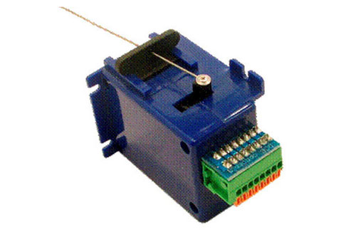
For this article we are going to concentrate on the under board mounting motors and show you how to wire them up for mimic panel control. We will be using a standard Setrack point with the SEEP GMC-PM1 motor. This motor has an inbuilt switch allowing it to control the mimic diagram without the need of another switch.
Installing the motors
Stage 1
The first step once you have purchased the required elements is to install the motor. Simply lay the point in the position you require it, and mark the throw of the motor. Use a pointed or retractable pencil, and put it through the hole in the tie bar. On Hornby points it is located in the centre, and on Peco, to one side. Then manually throw the point and you will have your mark. Then simply drill through the centre of the point with a 10mm drill bit, and you will have your hole, ready for your motor and point to be installed.
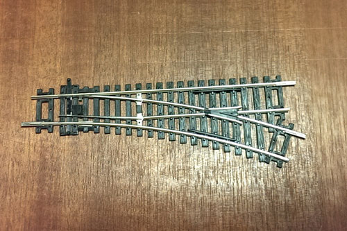
The point laid in place.
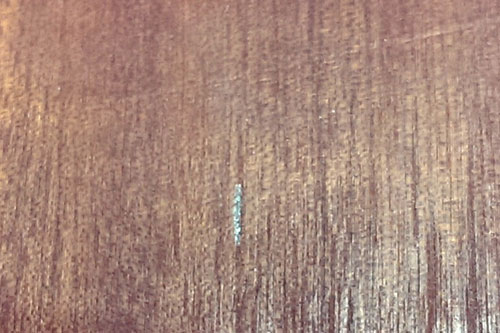
The mark left after removing the point.
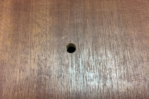
The hole left for the motor arm to connect to the point.
Stage 2
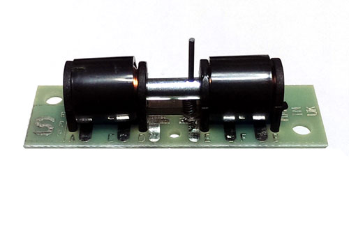
Next you need to solder up the motor terminals. When wiring up the motor and in built switch, you will need to solder six wires to the terminals A to F. I would advise you use a minimum of four colours to enable you to trace the wires easily if a problem ever occurs. Terminals A, B, and C are used for the control of the motor. If using four colours of wire I would recommend using one colour for terminals A and B and a second for terminal C. If you are able to, use six colours of wire, one for each terminal. Strip the end of the wire, about 5mm is best, and solder onto the terminals. Then repeat the same process for the switch terminals, terminals D, E, and F, keeping terminals D and E the same colours if wire is limited. At this point I would recommend keeping the wire to around 4 to 6 inches in length.
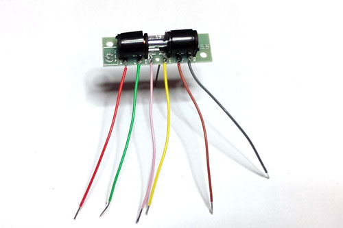
The motor with all six wires attached.
Stage 3
The next step is to install the point and motor. Pin your track down to the baseboard as you normally would. The next part can be the fiddly bit. From under the board you need to feed the motor arm through the tie bar and screw it to the base board. When doing this, take care to check that the point is throwing sufficiently and that the switch on the motor is aligned with its contacts in the position of each throw. Once this is installed you are ready to wire it in.
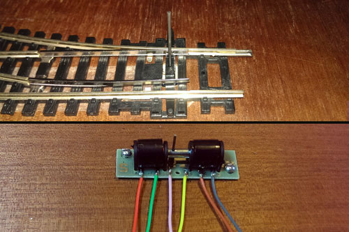
The motor is fitted under the board with the arm through the points tie bar.
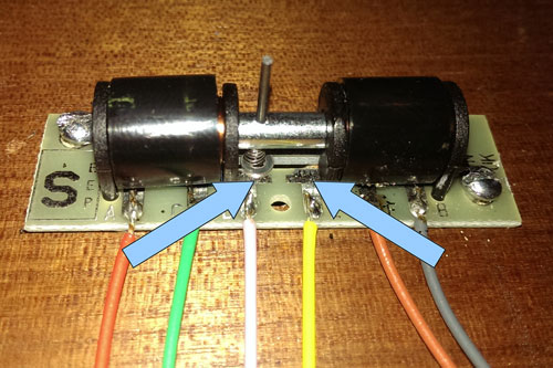
These are the two contacts for the switch, make sure centre spring is touching them when it is at either end of the throw.
Stage 4
CAUTION: When using electricity, never work on any circuit without TURNING IT OFF FIRST.
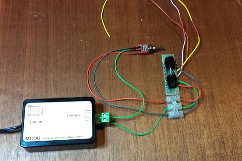
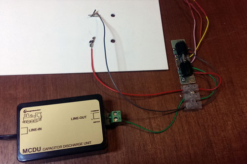
Once you have installed the motor, it's time to wire it in. The first thing to do in install the CDU. This is a unit that allows enough power to be given to each motor without over powering it and burning out the coils. You only need one of these per layout as it is only activating one or two motors at a time. If you are using the GM77 terminal block, simply connect all the wires of your motors into one side of the block. The next thing to do is connect the wire from terminal C to one side of the output from the CDU. We are working on AC power here so it doesnt matter which side it is connected to. If you are not using the GM77 terminal block, simply extend the wire with another length of wire by soldering them together, and sealing the joint by sliding a length of heat shrink and sealing it by heating it gently with a lighter.
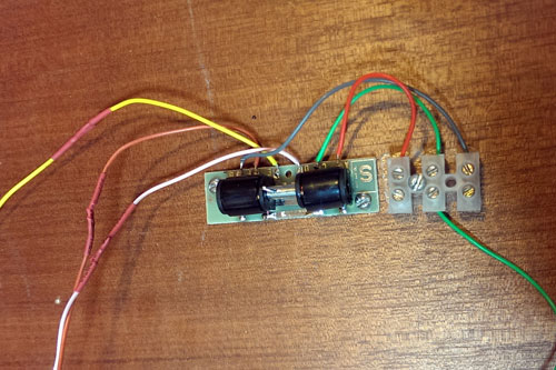
This motor has been wired up, half using the GM77 terminal block method and the other half using the heat shrinking method.
Stage 5
Now that the motor is installed and the power feed to it ready, we need to install the method of switching. As mentioned before there are a couple of ways of controlling the motor. The most favoured are by use of a toggle switch (GM510) or via a stud and probe. The switch is easy to install but does end up being more expensive than the stud and probe method. Once the decision has been made it's time to design your control panel. This is generally a sketch of the layout track plan, or one generated in a layout design program on a computer. Either one is then mounted onto a sheet of thin wood or plasticard. Holes are then drilled to fit either the switches or the studs and the LEDs.
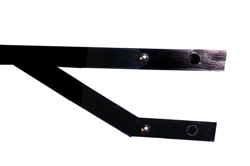
For this article I have used a diagram for a single point, in reality the panel would be larger showing all points on the layout.
If you are using switches:
If you are using switches to control your point motors, the next step is to install them. First decide where they are going to be situated. Are they going to be numbered switches lined up in a row with their number referring to the corresponding points? Or are they going to be installed into the panel.
Once you have decided and located them into place, simply solder a wire onto the three terminals. User the same colour wire on the outer two terminals as you have on terminals A and B on the point motor. Use the same colour as you have on terminal C and solder this to the centre terminal of the switch. Next simply connect the outer two wires to terminals A and B on the point motor in the same way as you did before; either via a terminal block, or by soldering and heat shrinking.
The point motor with terminals A and B wired to the switch.
If you are using Studs and Probe:
If you have decided against using switches, and instead want to use the stud and probe method you now need to install the studs. These simply push through the pre drilled holes. The pack of studs also comes with little washer-like terminals onto which you need to solder a wire. For each point you need two studs and two washers. As with the switch use the same colours of wire for the washers as you have for terminals A and B. once soldered up they can be pushed over the studs, with the studs being opened up like a split pin, securing the wires in place. Finally connect these wires to the wires from terminals A and B on your point motor.
The result once the two parts of the stud have been installed.
Stage 6
If you are using switches:
The final stage for wiring up the motors is simple. All you need to do now is attach the third wire from the switch to the second terminal on the CDU. Once this is done simply connect your CDU to the mains via the supplied transformer and test the motor,then you can disconnect the CDU and move onto installing the LEDs.
If you are using Studs and Probe:
The final stage of wiring up the motors is simple, all you need to do now is attach the probe. The wire from the probe simply connects to the second terminal on the CDU. If the wire isn't long enough, extend it as required. Once this is done simply connect your CDU to the mains via the supplied transformer and test the motor. Now you can disconnect the CDU and move onto installing the LEDs.
Installing the LEDs
Once the motor is installed and working, it is time to install the LEDs. This is the easy part.
If you are using the pre-wired LEDs from DCC Concepts:
Once you have installed the LEDs into the mimic diagram, take the black wire from two LEDs and temporarily attach them together, then extend the wire to one side of your 12 volt power supply. Then connect one of the red wires to the wire from terminal D and the second red LED wire to the wire from terminal E. To complete the circuit connect the wire from terminal E on the motor to the other side of your 12 volt transformer.
Now that they are wired in, plug in your transformer and test the circuits. If the LEDs are showing the incorrect route disconnect the transformer form the mains and switch the red LED wires to the other wire from the motor. For example if initially you attached the first LED to the terminal A wire and the second to the terminal B wire, reverse them so that the first LED is connected to the wire from terminal B and the second to the wire from terminal A. Your LEDs should now be working correctly. Now connect the wires together via a terminal block or by soldering and heat shrinking them.
If, when you switched on the transformer, none of the LEDs lit up then you need to swap the two wires on your power supply over. Disconnect them, reverse them, and put them back into the transformer.
Now that you have done this for one point motor, repeat the process for all your other points. The first time you do this it will take a little while, but the more motors and LEDs you install the quicker you will get until it becomes second nature.
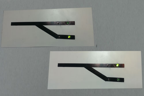
The finished board, simply duplicate the wiring for all your points for a fully functioning LED mimic panel.
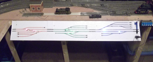
James works full-time in our shop here in West Sussex, and is a bit of an electrical whizz-kid as you can see! Above is a picture if a mimic panel James has built for a layout, click it for a closer look.
These motors, as the name suggests are mounted under the board. They either clip directly to the bottom of the point, or require attaching to the board below. These motors are perfect for those situations where there is space under the board to house them, and allow the motors to be hidden away from general view. They offer the ability to be able to control frog switching, signals, and mimic diagrams.
Surface mounting motors
As you may have guessed, these motors are designed to be mounted on top of the board. They are quick and easy to install as you don't need to cut out any holes for the motor mechanism to interact with the point. Instead they sit next to the motor on the side and have a little mechanism connected to the tie bar of the point. The one down side of these motors is that they are currently unable to control anything other than the throw of the points.
Slow action motors
These motors offer a different method of point control. The aforementioned motors both give a quick throw of the point motor, which is prototypically unrealistic. Slow action motors give a much more realistic throw to the points, mimicking that of an actual point throw. Although they may be more expensive than the other types of motor they do allow control of more than one other function, for example frog switching and mimic panel LEDs.
For this article we are going to concentrate on the under board mounting motors and show you how to wire them up for mimic panel control. We will be using a standard Setrack point with the SEEP GMC-PM1 motor. This motor has an inbuilt switch allowing it to control the mimic diagram without the need of another switch.
Installing the motors
Stage 1
The first step once you have purchased the required elements is to install the motor. Simply lay the point in the position you require it, and mark the throw of the motor. Use a pointed or retractable pencil, and put it through the hole in the tie bar. On Hornby points it is located in the centre, and on Peco, to one side. Then manually throw the point and you will have your mark. Then simply drill through the centre of the point with a 10mm drill bit, and you will have your hole, ready for your motor and point to be installed.
The point laid in place.
The mark left after removing the point.
The hole left for the motor arm to connect to the point.
Stage 2
Next you need to solder up the motor terminals. When wiring up the motor and in built switch, you will need to solder six wires to the terminals A to F. I would advise you use a minimum of four colours to enable you to trace the wires easily if a problem ever occurs. Terminals A, B, and C are used for the control of the motor. If using four colours of wire I would recommend using one colour for terminals A and B and a second for terminal C. If you are able to, use six colours of wire, one for each terminal. Strip the end of the wire, about 5mm is best, and solder onto the terminals. Then repeat the same process for the switch terminals, terminals D, E, and F, keeping terminals D and E the same colours if wire is limited. At this point I would recommend keeping the wire to around 4 to 6 inches in length.
The motor with all six wires attached.
Stage 3
The next step is to install the point and motor. Pin your track down to the baseboard as you normally would. The next part can be the fiddly bit. From under the board you need to feed the motor arm through the tie bar and screw it to the base board. When doing this, take care to check that the point is throwing sufficiently and that the switch on the motor is aligned with its contacts in the position of each throw. Once this is installed you are ready to wire it in.
The motor is fitted under the board with the arm through the points tie bar.
These are the two contacts for the switch, make sure centre spring is touching them when it is at either end of the throw.
Stage 4
CAUTION: When using electricity, never work on any circuit without TURNING IT OFF FIRST.
Once you have installed the motor, it's time to wire it in. The first thing to do in install the CDU. This is a unit that allows enough power to be given to each motor without over powering it and burning out the coils. You only need one of these per layout as it is only activating one or two motors at a time. If you are using the GM77 terminal block, simply connect all the wires of your motors into one side of the block. The next thing to do is connect the wire from terminal C to one side of the output from the CDU. We are working on AC power here so it doesnt matter which side it is connected to. If you are not using the GM77 terminal block, simply extend the wire with another length of wire by soldering them together, and sealing the joint by sliding a length of heat shrink and sealing it by heating it gently with a lighter.
This motor has been wired up, half using the GM77 terminal block method and the other half using the heat shrinking method.
Stage 5
Now that the motor is installed and the power feed to it ready, we need to install the method of switching. As mentioned before there are a couple of ways of controlling the motor. The most favoured are by use of a toggle switch (GM510) or via a stud and probe. The switch is easy to install but does end up being more expensive than the stud and probe method. Once the decision has been made it's time to design your control panel. This is generally a sketch of the layout track plan, or one generated in a layout design program on a computer. Either one is then mounted onto a sheet of thin wood or plasticard. Holes are then drilled to fit either the switches or the studs and the LEDs.
For this article I have used a diagram for a single point, in reality the panel would be larger showing all points on the layout.
If you are using switches:
If you are using switches to control your point motors, the next step is to install them. First decide where they are going to be situated. Are they going to be numbered switches lined up in a row with their number referring to the corresponding points? Or are they going to be installed into the panel.
Once you have decided and located them into place, simply solder a wire onto the three terminals. User the same colour wire on the outer two terminals as you have on terminals A and B on the point motor. Use the same colour as you have on terminal C and solder this to the centre terminal of the switch. Next simply connect the outer two wires to terminals A and B on the point motor in the same way as you did before; either via a terminal block, or by soldering and heat shrinking.
The point motor with terminals A and B wired to the switch.
If you are using Studs and Probe:
If you have decided against using switches, and instead want to use the stud and probe method you now need to install the studs. These simply push through the pre drilled holes. The pack of studs also comes with little washer-like terminals onto which you need to solder a wire. For each point you need two studs and two washers. As with the switch use the same colours of wire for the washers as you have for terminals A and B. once soldered up they can be pushed over the studs, with the studs being opened up like a split pin, securing the wires in place. Finally connect these wires to the wires from terminals A and B on your point motor.
The result once the two parts of the stud have been installed.
Stage 6
If you are using switches:
The final stage for wiring up the motors is simple. All you need to do now is attach the third wire from the switch to the second terminal on the CDU. Once this is done simply connect your CDU to the mains via the supplied transformer and test the motor,then you can disconnect the CDU and move onto installing the LEDs.
If you are using Studs and Probe:
The final stage of wiring up the motors is simple, all you need to do now is attach the probe. The wire from the probe simply connects to the second terminal on the CDU. If the wire isn't long enough, extend it as required. Once this is done simply connect your CDU to the mains via the supplied transformer and test the motor. Now you can disconnect the CDU and move onto installing the LEDs.
Installing the LEDs
Once the motor is installed and working, it is time to install the LEDs. This is the easy part.
If you are using the pre-wired LEDs from DCC Concepts:
Once you have installed the LEDs into the mimic diagram, take the black wire from two LEDs and temporarily attach them together, then extend the wire to one side of your 12 volt power supply. Then connect one of the red wires to the wire from terminal D and the second red LED wire to the wire from terminal E. To complete the circuit connect the wire from terminal E on the motor to the other side of your 12 volt transformer.
Now that they are wired in, plug in your transformer and test the circuits. If the LEDs are showing the incorrect route disconnect the transformer form the mains and switch the red LED wires to the other wire from the motor. For example if initially you attached the first LED to the terminal A wire and the second to the terminal B wire, reverse them so that the first LED is connected to the wire from terminal B and the second to the wire from terminal A. Your LEDs should now be working correctly. Now connect the wires together via a terminal block or by soldering and heat shrinking them.
If, when you switched on the transformer, none of the LEDs lit up then you need to swap the two wires on your power supply over. Disconnect them, reverse them, and put them back into the transformer.
Now that you have done this for one point motor, repeat the process for all your other points. The first time you do this it will take a little while, but the more motors and LEDs you install the quicker you will get until it becomes second nature.
The finished board, simply duplicate the wiring for all your points for a fully functioning LED mimic panel.
James works full-time in our shop here in West Sussex, and is a bit of an electrical whizz-kid as you can see! Above is a picture if a mimic panel James has built for a layout, click it for a closer look.
If you are using switches:
The final stage for wiring up the motors is simple. All you need to do now is attach the third wire from the switch to the second terminal on the CDU. Once this is done simply connect your CDU to the mains via the supplied transformer and test the motor,then you can disconnect the CDU and move onto installing the LEDs.
If you are using Studs and Probe:
The final stage of wiring up the motors is simple, all you need to do now is attach the probe. The wire from the probe simply connects to the second terminal on the CDU. If the wire isn't long enough, extend it as required. Once this is done simply connect your CDU to the mains via the supplied transformer and test the motor. Now you can disconnect the CDU and move onto installing the LEDs.
Installing the LEDs
Once the motor is installed and working, it is time to install the LEDs. This is the easy part.
If you are using the pre-wired LEDs from DCC Concepts:
Once you have installed the LEDs into the mimic diagram, take the black wire from two LEDs and temporarily attach them together, then extend the wire to one side of your 12 volt power supply. Then connect one of the red wires to the wire from terminal D and the second red LED wire to the wire from terminal E. To complete the circuit connect the wire from terminal E on the motor to the other side of your 12 volt transformer.
Now that they are wired in, plug in your transformer and test the circuits. If the LEDs are showing the incorrect route disconnect the transformer form the mains and switch the red LED wires to the other wire from the motor. For example if initially you attached the first LED to the terminal A wire and the second to the terminal B wire, reverse them so that the first LED is connected to the wire from terminal B and the second to the wire from terminal A. Your LEDs should now be working correctly. Now connect the wires together via a terminal block or by soldering and heat shrinking them.
If, when you switched on the transformer, none of the LEDs lit up then you need to swap the two wires on your power supply over. Disconnect them, reverse them, and put them back into the transformer.
Now that you have done this for one point motor, repeat the process for all your other points. The first time you do this it will take a little while, but the more motors and LEDs you install the quicker you will get until it becomes second nature.
The finished board, simply duplicate the wiring for all your points for a fully functioning LED mimic panel.
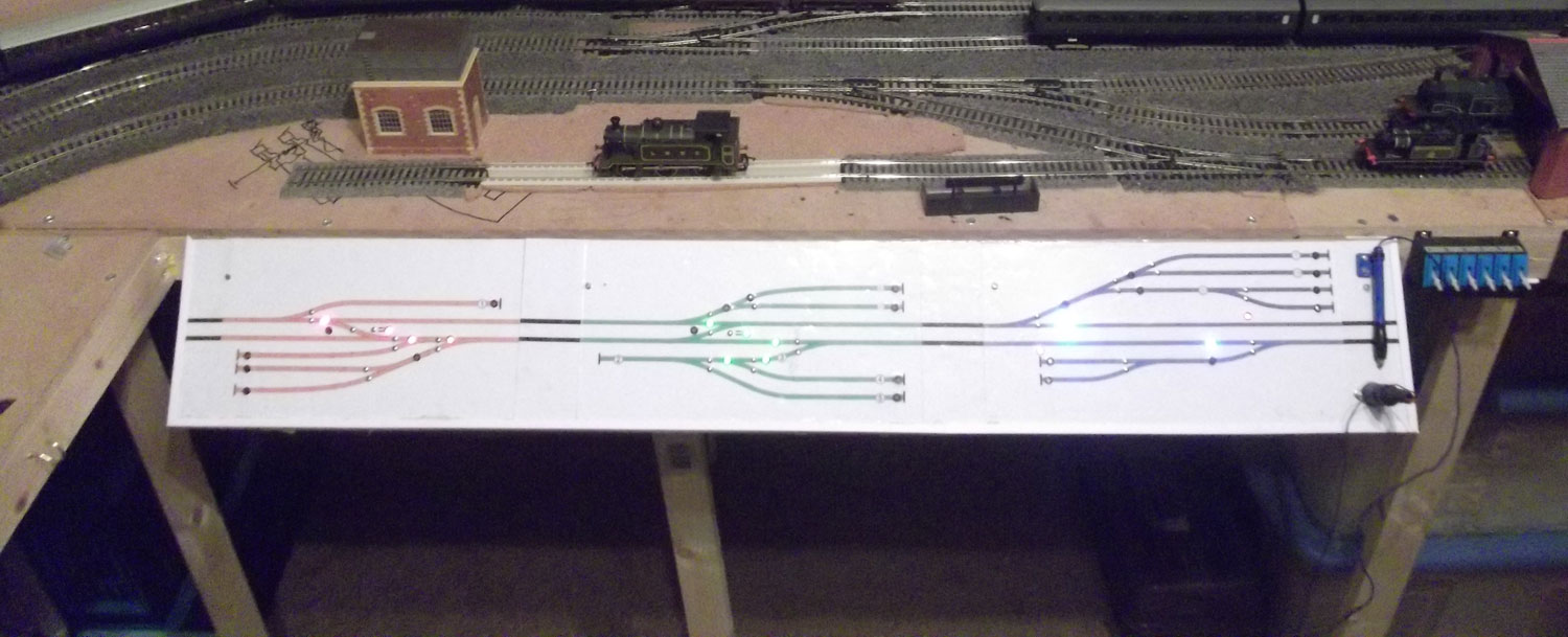
James works full-time in our shop here in West Sussex, and is a bit of an electrical whizz-kid as you can see! Above is a picture if a mimic panel James has built for a layout, click it for a closer look.
|


We are always looking to make improvements to our website to try and improve the quality of your visit. We would welcome your feedback and suggestions, so please do not hesitate to e-mail our webmaster with your comments. Alternatively call us on 01903 884488.
Home Cookies Privacy Statement Terms & Conditions Site Map Site Guide
WEEE Regulations Glossary Careers & Jobs
Tel – +44 (0) 1903 884488 Fax – +44 (0) 1903 884377 E-Mail us – click here
Gaugemaster.com is a trading name of Gaugemaster Controls Ltd.
Registered in England No. 2714470, Registered office:
Gaugemaster House, Ford Road
Arundel, West Sussex, BN18 0BN, United Kingdom
VAT Reg. No. 587 8089 71
Copyright © 2003-2014 Gaugemaster Controls Ltd. All Rights Reserved.