|
| OO Scale | N Scale | G Scale | Z Scale | HO Scale | Slot Cars & R⁄C |
| |||||||
|
|||||||
| Home Page | |||||||
| BUY GIFT VOUCHERS | |||||||
| Products | |||||||
| Latest News | |||||||
| RIGHT LINES | |||||||
| Bargains | |||||||
| Downloads | |||||||
| Events | |||||||
| Careers & Jobs | |||||||
| Carriage Services | |||||||
| About Us | |||||||
| Contact Us | |||||||
| Pay Us A Visit | |||||||
| Meet The Staff | |||||||
| Links | |||||||

| SHOPPING BASKET |
Your shopping basket is empty. To add an item, click the "Buy" button
| YOUR ACCOUNT | ||
|
||||
 |
||||
| Prodigy Advance Digital System |
||||
| Cased Controllers |
||||
| Panel Mount Controllers |
||||
| Walkabout Controllers |
||||
| Modules & Transformers |
||||
| Scenics & Accessories |
||||
| Wiring & Electrical Components |
||||
| Tiny Signs | ||||
| Tools | ||||
 |
||||
| RECENTLY VIEWED |
| OD76SHL06WF - Stobart Lorry Tony McCoy | ||
| OD76DXF007 - DAF XF Euro 6 Semi Low Loader Pollock Lift & Shift | ||
| FA180914 - Blue Dumpsters (2) Kit | ||
| ODNFT034 - Ford Transit MkV Van Parcelforce | ||
| PK62228 - Red River Station Kit | ||
| More ›› |
| O Scale | Wargaming | Architectural | Narrow Gauge | Tools+ | ||
Programming Accessory Decoders with Prodigy

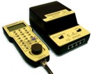
GREG SPEARS explains how to programme accessory decoders using the Gaugemaster Prodigy DCC system.
As you are all now familiar with programming loco addresses on the Prodigy (if you're not click here). We will now look at the two most common types of accessory / point motor decoders and how to set them up.
The main types of decoders are ones you program with the controller much like a loco decoders - and learning decoders which typically these are used on motor driven "slow action" motors and traditional solenoid motors. A third type is the servo style systems but these will be covered in more detail as a separate article.
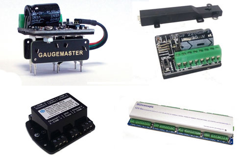
There are lots of decoders on the market, so remember this is a guide and the manufacturer's decoder instruction should always be the first place of reference. Let's start with the programmable type of decoder such as our DCC30 and the Hornby R8247.
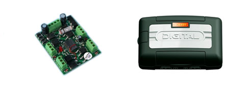
Both of these units require connection to the programming track on the Prodigy and adjusted via various CV's to change address and type of output. Note the older Hornby decoder that looked identical did not work in this manner, and was more specific to the Hornby system. So we will concentrate on the DCC30 but the principal for the Hornby and many other decoders will be the same but check the instructions for specific values.
Once connected to your programming track go into Pro9 Prog Track on your controller.

Then using the SHIFT key skip through to CV#.

Here we key in the address CV which on the DCC30 is 513 and press ENTER, The display will now ask for Data.

These decoders are numbered 1-4 as standard so logically your next unit will be 5-8, to set it you simply key in the first number in the sequence. So key in 5 and press ENTER, the unit will display the SEnd message and the led in the DCC30 will also blink.

The four outputs on the decoder can be coded up to 127 but note it must be in the same groups 1-4 5-8 9-12 13-16 etc.
On a DCC30 there is a short link wire that needs to be cut for a pulsed output and always program all outputs to ensure the correct length of pulse.
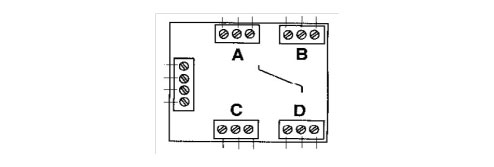
Each output has its own individual CV number; outputs A-B-C-D are CV515 - 516 - 517 518 and can be set to different values to change their output style. Before use we always advise customers to set the output style, for solenoid decoders we suggest you start with a short pulse such as 2. So with your decoder still connected to the programming track key in to CV# 515 and press ENTER, when it requests Data key in 2 and press ENTER to SEnd. Repeat this operation for CV516 517 518. Once completed the decoder is ready for use on the layout. The DCC30 can be set for a longer pulse simply by increasing the Data to a higher number but only go in small increment as an excessively long pulse could damage a point motor. The value of 1 to 127 is used for a pulsed output and 0 and 128 is a latched output, a latched output is not normally suitable for solenoid use. If you look at the DCC30 instructions you will see other options like flashing lights and delayed operation but we will just stick to the basics for now. If the direction of the motor is incorrect simply reverse the outer output connections, most accessory decoder outputs are DC and common positive which can make a big difference if connecting signals etc.
Now the next type of accessory decoder, like the ones used on our GMC-PM10D, GMC-PM20D, Train-Tech and Cobalt Digital. These are learning decoders.
These are very popular, as they are quick and simple to set up - however they are not as adjustable as the programmable units. To set one up simply install it into your layout following the connections in the manufacturer's instructions. Once connected simply press your Accessory button on your handset and key in the number 1 followed by ENTER, the display will now display the Accessory number and the numbers message 1 or 2.

Press button 1 or 2 to toggle between On and OFF.


Now once you have got to this stage set the decoder into its set or learn mode via its switch or button, then press either button 1 or 2. Whichever you choose, there must be only one key press before returning the decoder switch to its normal position, or waiting for confirmation from the decoder. This stage is the most important as two button presses will confuse the decoder which then typically ignores the command. The address you choose will, if done correctly, be the address the decoder programs itself, and the direction can also be selected depending on if button 1 or 2 is used to activate it. Most of these types of decoders have limited adjustments as they are designed for a specific purpose but are equally as capable.
|


We are always looking to make improvements to our website to try and improve the quality of your visit. We would welcome your feedback and suggestions, so please do not hesitate to e-mail our webmaster with your comments. Alternatively call us on 01903 884488.
Home Cookies Privacy Statement Terms & Conditions Site Map Site Guide
WEEE Regulations Glossary Careers & Jobs
Tel – +44 (0) 1903 884488 Fax – +44 (0) 1903 884377 E-Mail us – click here
Gaugemaster.com is a trading name of Gaugemaster Controls Ltd.
Registered in England No. 2714470, Registered office:
Gaugemaster House, Ford Road
Arundel, West Sussex, BN18 0BN, United Kingdom
VAT Reg. No. 587 8089 71
Copyright © 2003-2014 Gaugemaster Controls Ltd. All Rights Reserved.